STRUCTURE TEMPORARY AND DEMOUNTABLE: TRESpuntoCERO,
Juan Felipe Talamás Salazar. Architect, UPC, Barcelona, España,
juantalamas@hotmail.com
ABSTRACT. Thinking about the issue of natural disasters such as earthquakes, earthquakes, hurricanes, epidemics, is very important to consider the rapid action of NGOs (Non-Governmental Organizations), and international community in general, to give provisions of food, medicines, medical care, emergency housing, etc.
Focusing more specifically on healthcare and emergency housing, it’s of vital importance the quick construction of the necessary installations because in this context, time means human lives. If we spent more time on the construction of a hospital or home it cause a delay in the medical care and housing which the people who are living these natural disasters urgently needed.
This article develops a proposal to solve this problem specifically with a construction system that can respond to various needs, including and most important, there is a medical module and quality housing.
This construction system is called TRESpuntoCERO, which has the characteristic of expanding its area three times its original size (hence its name), offers as main advantages quickly install, requires no skilled labor, it works temporarily independently without the need of connection to electricity, water, sewer or gas, with the ability to quickly mount the module, put it to use, and remove it from the site without problem depending on the needs.
Fig. 01 Module TRESpuntoCERO closed.
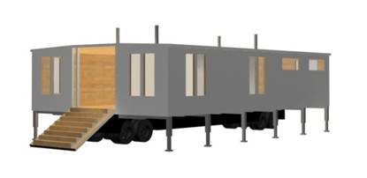
Fig. 02 Module TRESpuntoCERO opened
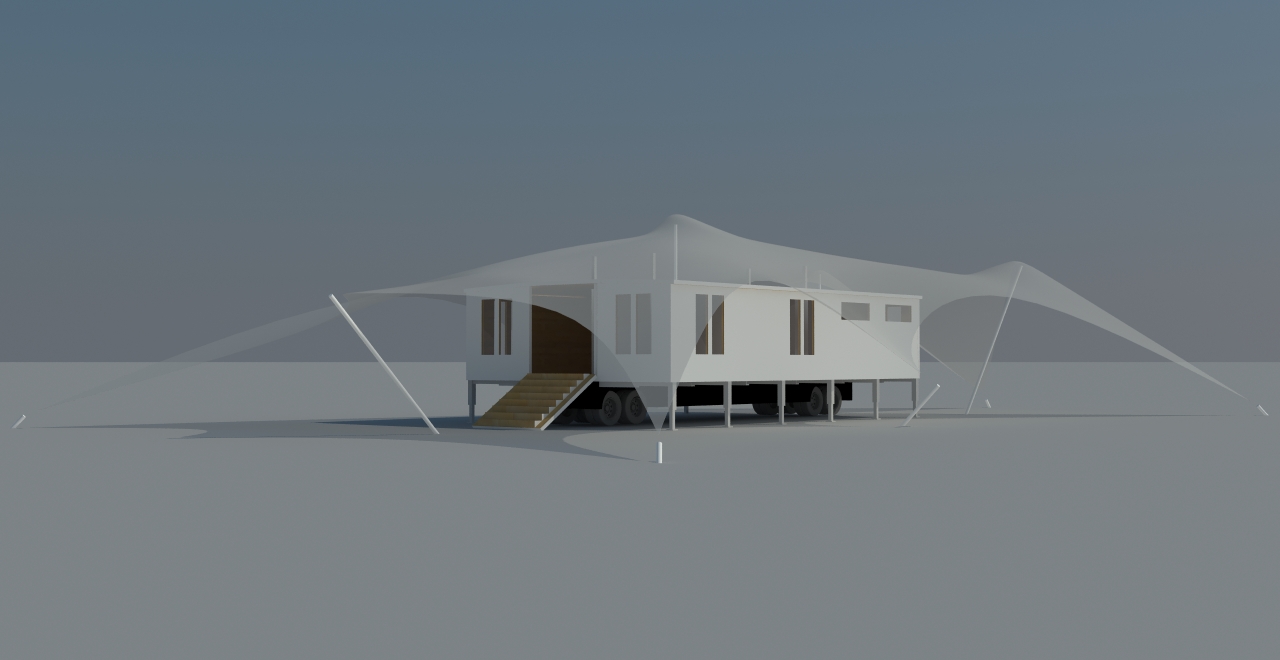
Finally, the module is covered by a tensile structure that brings protection of the outdoor (Fig. 03).
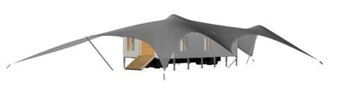
Fig. 03 Module TRESpuntoCERO opened whit the tensile structure.
And likewise, this module can be copied as often as necessary and connect them to generate an even larger space. It’s also possible to mount a module on the first ones (without the bottom of the module system) to generate a second floor as well as seen in the figure 04.
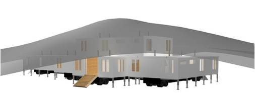
Fig. 04 Multiple Modules TRESpuntoCERO opened whit the tensile structure.
MOVEMENTS
The movements are described step by step in the title of each of the figures:
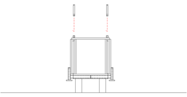
Fig. 05 Placement of the top posts, which ones will be hold the mobile roof.
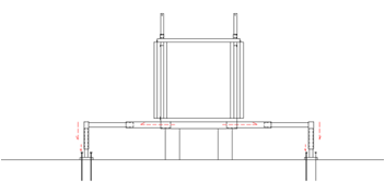
Fig. 06 Assembly of the lower telescopic system and at the bottom of the module which is attached to the ground with stakes passing through the bottom plates of the supports.
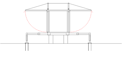
Fig. 07 The mobile roof is raised in this direction. At this moment, the upper posts are holding it to preventing falls.
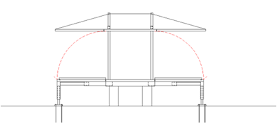
Fig. 08 The floor is lowered in this direction and is supported by the lower structure. The façade panels are already integrated in the floor panels.
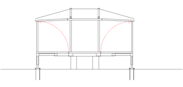
Fig. 09 The wall panels are raised and thus the mobile roof is supported on the facade panels which distribute the load to the lower hydraulic system.
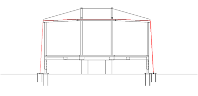
Fig. 10 Then is placed a series of cables which are subject to lower plates with stakes driven to ensure reliable anchoring of the module to the ground and preventing the wind can lifting it.
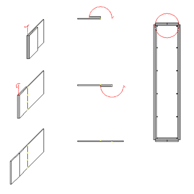
Fig. 11 Finally, to close the entire module, on the other sides of the module, two panels unfold like an accordion closing the complete module.
ACCESS
When the module is opened, it has on the lateral fixed panels (marked with red in Fig 12) that are used as access to the interior. There are two ways to get on the module, with stairs that fold down from the inside (Fig. 13) and in given case of accessibility, it is possible to place a hydraulic ramp (Fig. 14)
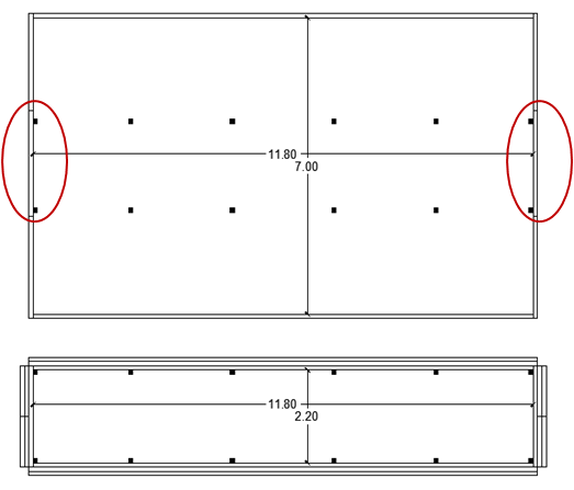
Fig. 12 Top view of the closed and opened module.
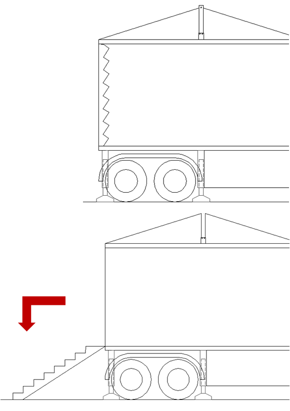
Fig. 13 Access with stairs
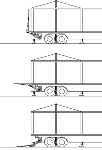
Fig. 14 Access with ramp
DISTRIBUTION
At the top of the module is where the user gives the life of the project depending on the needs like housing, health center, commercial, etc. (Fig. 15). While at the bottom are placed all services such a battery, a water tank and storage tank for sewage water that make the module independent temporarily (Fig. 16). The wiring for the electrical pass through the floor and up through the inside of the metal pillars (Fig. 17).
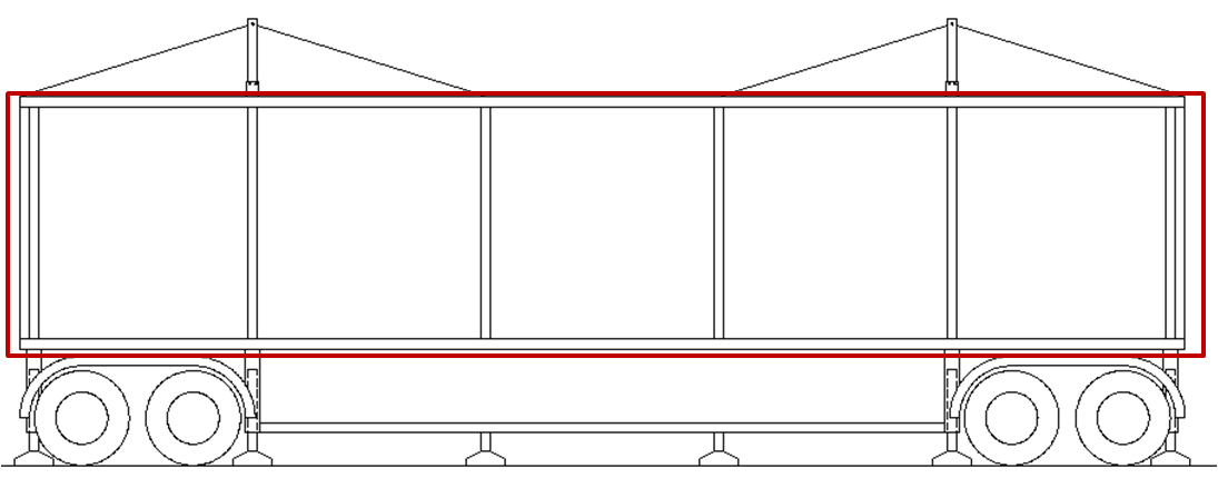
Fig. 15 Section of the open module
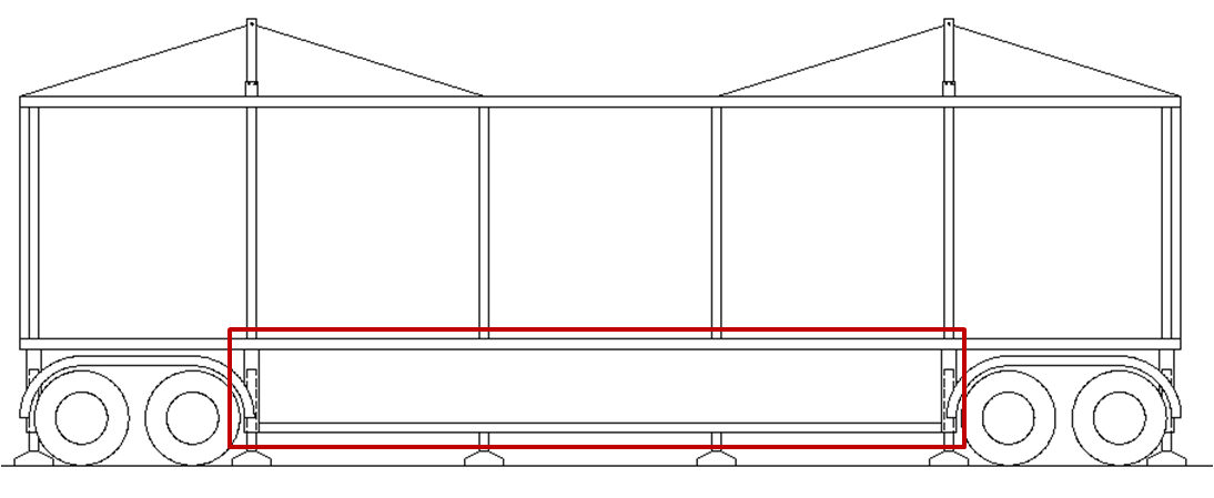
Fig. 16 Section of the open module
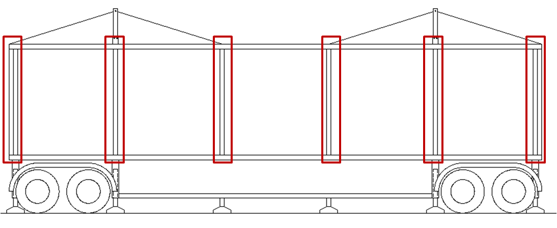
Fig. 17 Section of the open module.
JOIN DETAILS
Because of all the movements, the subject of the joints is very important to prevent water seepage and protect thermal bridges. For this, it will be shown the main joints and their solutions. The panels are simply a layer of plywood on the inside and the outside with different finishes, leaving space therein for placement of a thermal insulator. The structure of the panels is reinforced with solid wood bar and end with solid wood at the edges.
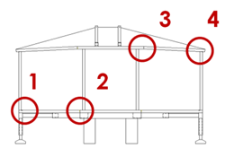
Fig. 18 Section of the module showing the main joins
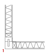
Fig. 18.1 In this corner is shown as solid wood edges are coupled separate a piece of wood that is placed before placing the facade and is fixed by the geometry.
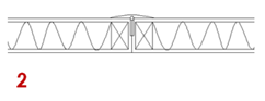
Fig. 18.2 For this join requires a hinge that is 180 degrees and then place a piece of plastic to prevent accidents.
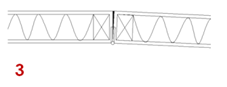
Fig. 18.3 This inclination allows to have a slope that prevents water can remain stagnant in the upper part. There can place a thermal sponge called Tesamoll to avoid thermal bridges.
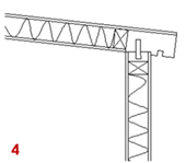
Fig. 18.4 This join is similar to the no. 1 as it is a separate item on the edge of the front panel and the roof fits together and becomes a glob of solid wood to prevent stains on the facade.
In the other direction of the module, there are generated different joins that are resolve with a plastic strip along the length of the panel that allows a “click” system where simply moving the panels, when its gets parallel, are anchored and get fixed.
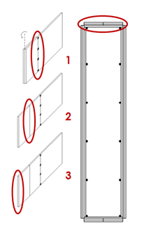
Fig. 19 Isometric and plan view showing joins
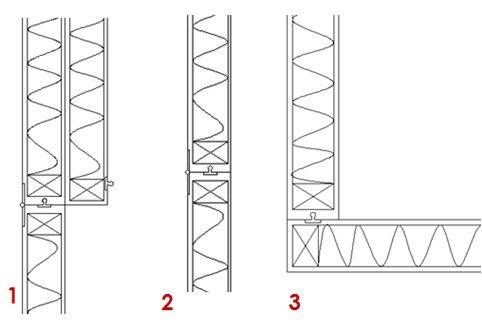
Fig. 19.1 Details of the joins.
TENSILE STRUCTURES
For effects of this proposal, I suggests Serge Ferrari brand model Stamisol FT381 as it protects the module rainwater, provide transparency and protection from solar radiation. Depending on the climatic characteristics can vary this tensile structure. (Fig. 20).
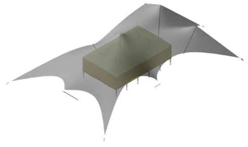
Fig. 20 Isometric view of the open module with the tensile structure.
In general, the cover protects from rain and as the module is separated from the ground, prevents leaks in the bottom of it in case of flooding (Fig. 21).
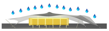
Fig. 21 Section view of the open module with the tensile structure.
Also, allows ventilation at the bottom and top of the module, which can take advantage with windows and holes in the slab to make the air can flow freely inside (Fig. 22).
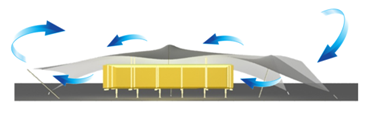
Fig. 22 Section view of the open module with the tensile structure.
And finally protects the fabric of the solar radiation, and mixed with venting causes the module is maintained at a comfortable temperature (Fig. 23).
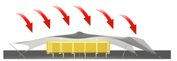
Fig. 23 Section view of the open module with the tensile structure.
POSSIBLE USES
This construction system is very wide and could give commercial uses, mobile home, temporary exhibitions, promotion, marketing, health care centers, emergency hospitals or emergency housing among others.
In Figure 24 we can see an application for emergency housing for 2 families of 4 persons each with separate entrances and the facility to make one complete module for 8 persons. In Figure 25 is an application for a family of 4 people where it has a large space, more privacy and comfort.
Both proposals already have everything its need and require no works on the outside or inside. The furnishings are foldable and convertible this to achieve that when the module is closed, can be compactly inside and travel whit the module, and when the module is open, this can be moved, put in place and deploy them to give necessary uses as beds, tables , shelves, etc.
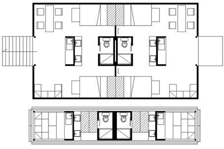
Fig. 24 Housing for 8 persons.
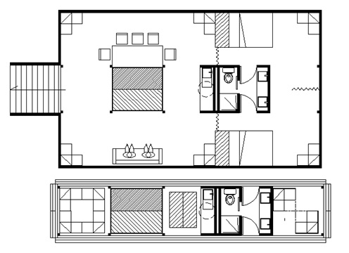
Fig. 25 Housing for 4 persons.
